Last time on the Raspberry Tank build diary, we figured out exactly what signals we would need to use to control the tank if we were to replace the TK-YL101-3 RF receiver board with the Raspberry Pi. This time around, we’re going to see if the Pi can actually generate that signal.
Step 1: Wiring Up
The Raspberry Pi comes with a 26-pin header that exposes GPIO pins, UART, SPI and I2C interfaces and 5/3.3V power, and it’s this that we’re going to use to generate the control signal for the tank. Specifically, one of the GPIO pins, as these can easily be switched on and off from software.
The eLinux Wiki provides an excellent summary of the pins on the Pi’s exposed header. Based on the diagram there, I chose to use GPIO 7 as the digital output that we will later wire into the tank – mostly because in position 26 on the header, it is easy to get to.
Unfortunately the Ground pin is not so easily accessible – the pitch spacing of the pins is not large, and in the course of testing I accidentally touched both Ground and the neighbouring UART Tx pin together with a crocodile clip. This caused an immediate restart of the Raspberry Pi. I was probably lucky to have hit those two, as doubtless there are some combinations that can cause permanent damage to the device.
Testing continued after the tactical deployment of sticky tape:
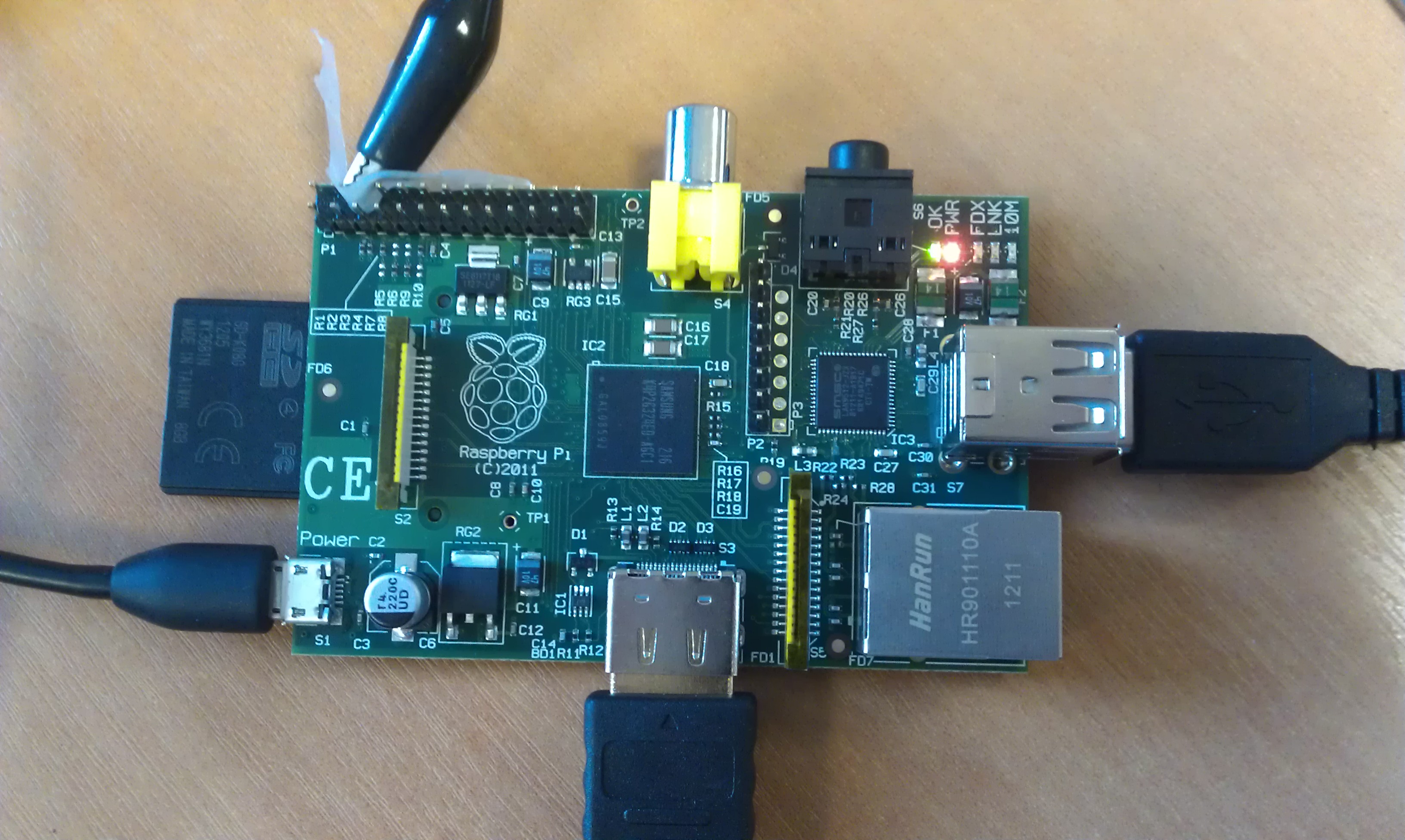
Raspberry Pi with Croc Clip attached to GPIO Ground
With this in place, the oscilloscope could now be connected to pins 26 (GPIO 7) and 6 (Ground) of the Raspberry Pi’s header, allowing us to see just what the device would be outputting.
Step 2: To the Compileatron!
Firstly, I wanted to make sure that a C program could toggle the GPIO bits fast enough to replicate the signal that the TK-YL101-3 board sends. Yesterday, we discovered that the shortest marks and spaces in the message were around 300 microseconds long, so my first program simply generated a square wave with a 600 microsecond period on GPIO 7. I based it on Gert & Dom’s example on the eLinux wiki. (I have not included source code for this program here – source is available below for my more advanced program that sends the correct command codes.)
The result of running this program was a pretty neat 3.3V, 600 microsecond square wave.
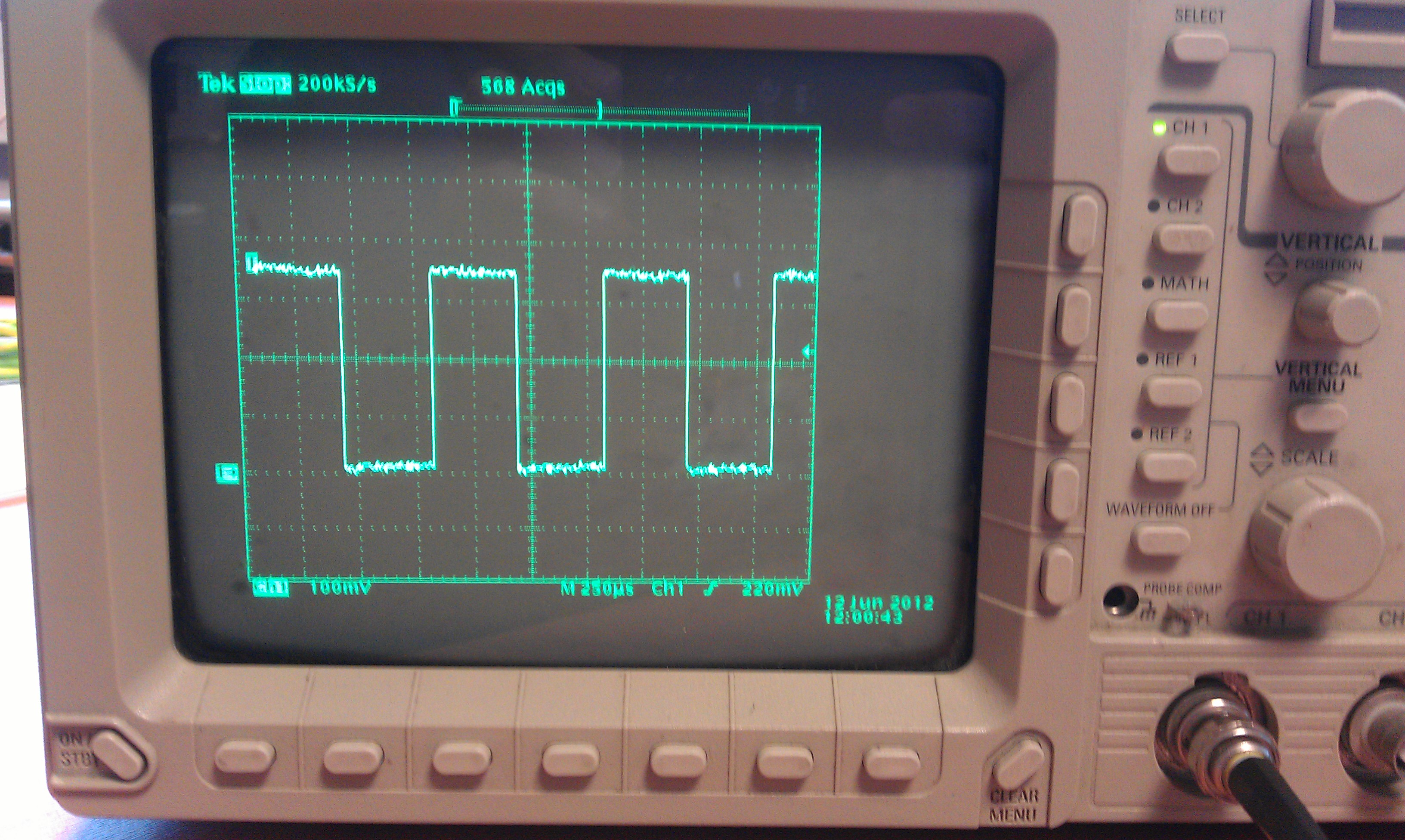
Square Wave on Oscilloscope
So, we can toggle the GPIO output line fast enough to do the job. But could we output the correct bit patterns to control the tank?
Step 3: Code Transmission
The next stage was to expand the program to transmit the control codes that the tank is expecting. Nothing too clever at the moment – the program simply sends the “idle” command for a while, followed by “ignition”, then sends “slow forwards” until manually halted.
This program was a complete success, reproducing almost exactly what the TK-YL101-3 chip produced, but with a couple of potential issues:
- The output of the Raspberry Pi’s GPIO pins is only 3.3V, compared to the 4V output of the TK board. There is no documentation on the input voltage range that the RX-18 board is expecting, so 3.3V may be enough, or it may not. I intend to add a transistor circuit between the Pi and the RX-18 anyway, so if necessary this can be used to bump up the voltage. There are several potential sources of 4.5V and 7.2V in the system, and if they are too high they can always be reduced with a potential divider.
- Despite the sleep timers in the C program matching the observed timings from the TK board, the entire pulse train ended up being around 25ms long rather than 20ms. This is likely due to the time taken to switch the GPIO output, but it could also be due to the Pi servicing various interrupts that take priority over my application’s timing. If this proves to be a problem when interfacing with the tank, the sleep timers can be reduced to bring the pulse train back to the proper length. We must also keep a careful eye on interrupts in future, as right now the Pi is doing little other than running one simple program – but that will not be the case if the Pi gains webcams, WiFi etc. in enhanced versions.
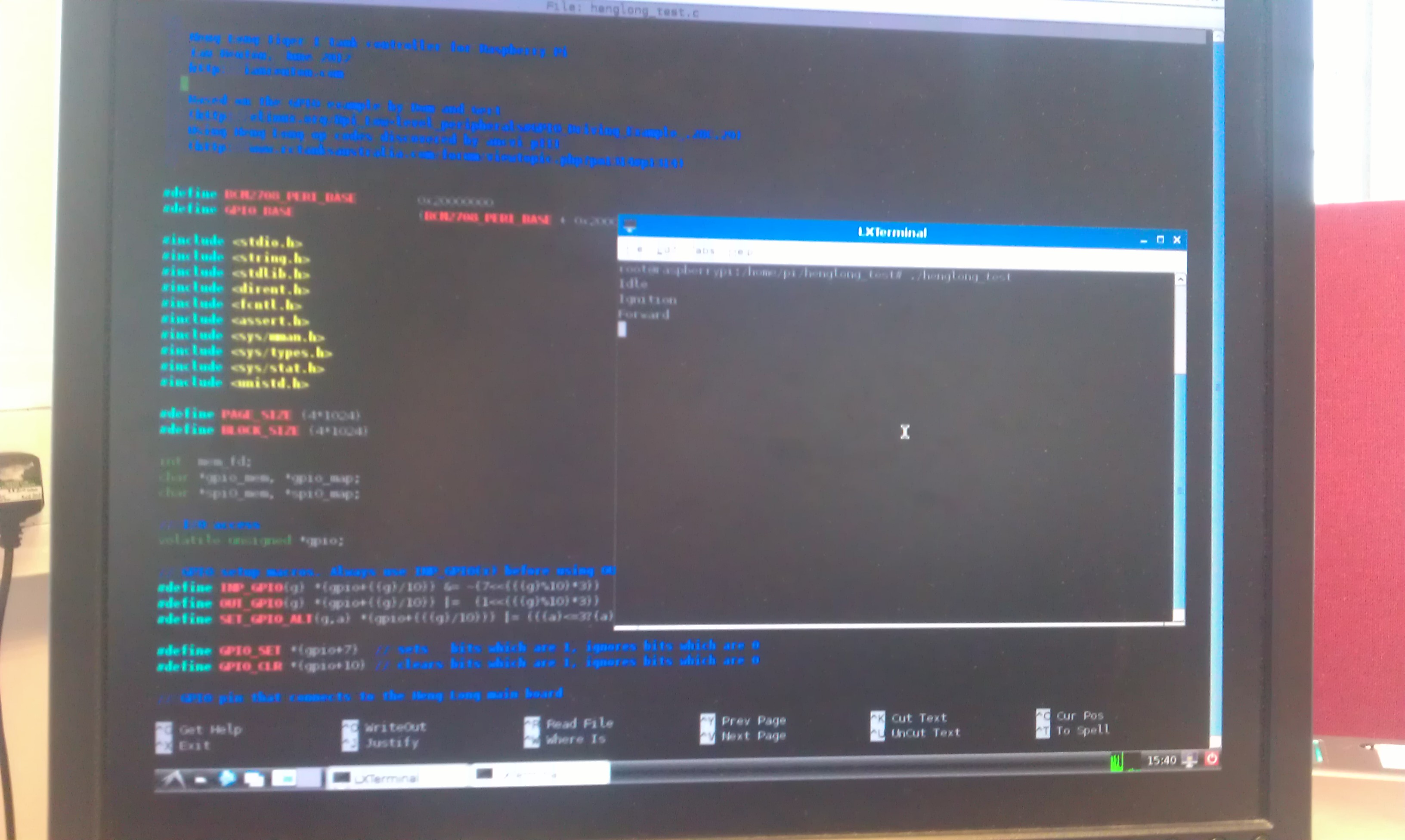
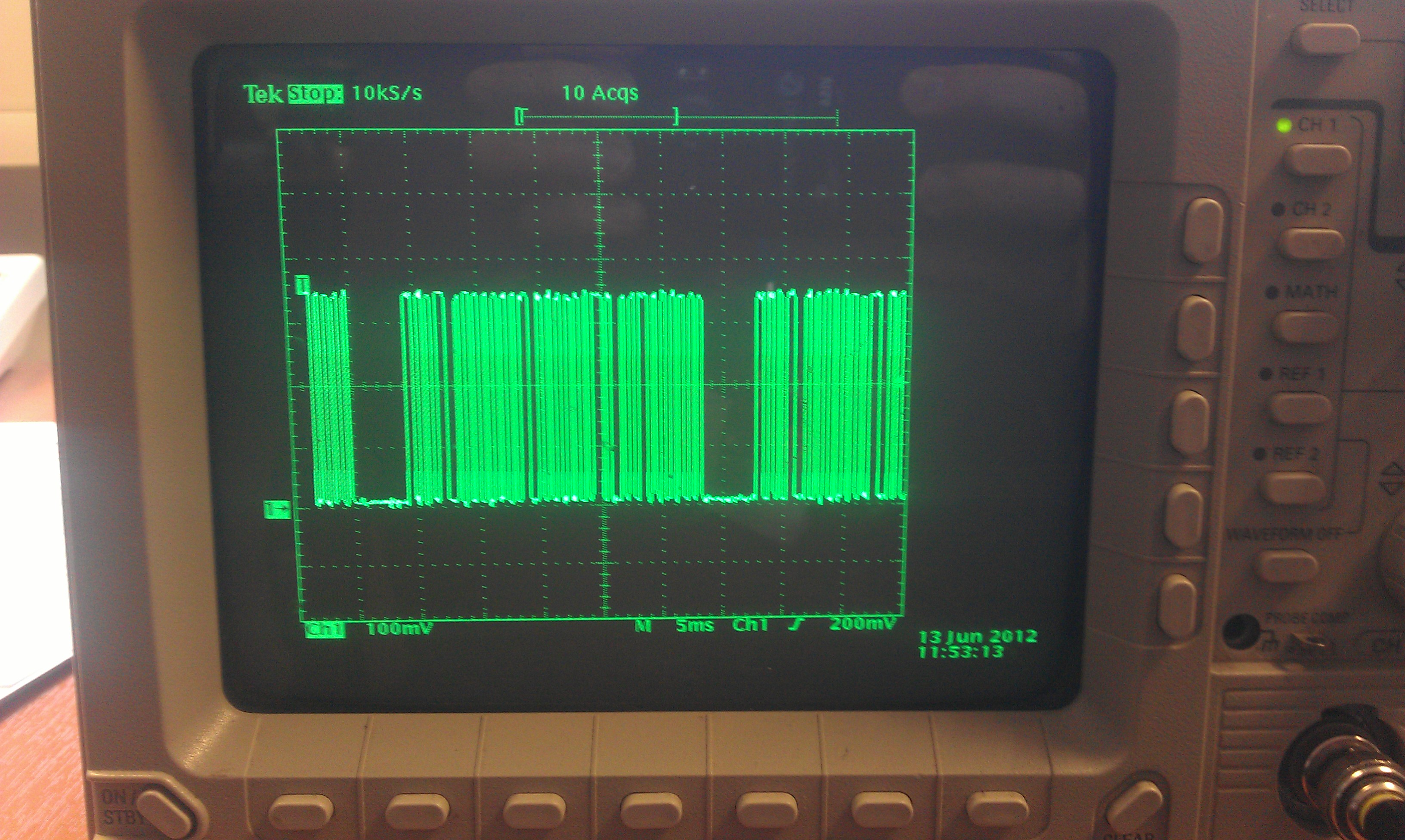
Code Running on the Raspberry Pi (left) and pulse train output (right)
You can find the source code for my program on GitHub. To download, build and run it on your Raspberry Pi (assuming you’re using the standard Debian image), you can run the commands below – though bear in mind that they will download the latest version of the test program, which may differ from the one linked above.
Warning:The first command below makes subsequent commands run as the root user. You must be root to use the Raspberry Pi’s GPIO. However, bear in mind that downloading unknown code from the internet, compiling it and running it as root is about the most dangerous thing you can do with your computer! Before running this or any other code you download, you should really read the source – that way you can check that it’s not malicious, and also figure out how it works!
sudo su
wget https://raw.github.com/ianrenton/raspberrytank/master/henglong_test.c
gcc henglong_test.c -o henglong_test -v
chmod +x henglong_test
./henglong_test
If you see “Idle”, followed by “Ignition” and “Forward” on the screen, it’s working!
Comments
I absolutely love your project. It's the coolest use I've yet seen for a Raspberry Pi.
I've got to admit though that that I had noticed you hadn't posted any warning note next to a code snipped which basically goes:
1) Deactivate your security
2) Order your computer to download and compile a set of unvetted code from the internet.
4) Run it as root.
I think npm has a really important 1 line warning next to its simillar script: http://npmjs.org/
I'm only a little nervous about it because the raspberry pi is supposed to be a kids platform, and I think it would be really cool if the community made an effort to make sure all the awesome project documentation teaches young coders good habits.
That's entirely fair! I've added what I think is a suitable warning -- what do you think?
Have you considered doing the bit timing in kernel space? An example could be seen here:
http://www.raspberrypi.org/phpBB3/viewtopic.php?f=37&t=11159
I did wonder if I'd have to, but I tried to avoid it as I'd never done any kernel module development before. As it turned out, usleep() in C is good enough to produce the timing I need -- in fact, the timing is more reliable using this method than it was using the original RF receiver board!
Thanks for the link though, I'll keep it in mind if I need to do any higher frequency control.
Благодарю всем кто не игнорил. Благодарю всех. Большое спасибо юзеру Admin