On Day 4 of the Raspberry Tank build diary, we figured that the best way of putting the Pi in control of this tank would be to remove the TK-YL101-3 board that normally receives and decodes the RF signal from the remote control, and get the Pi to replicate the commands it sends to the main controller. The underwater vehicle autonomy community often refers to this as the “backseat driver” paradigm – one processor handles things like missions and behaviours (the Raspberry Pi, in this case) while another handles things like motors and firing mechanisms (here, the RX-18).
Step 1: Wiretapping
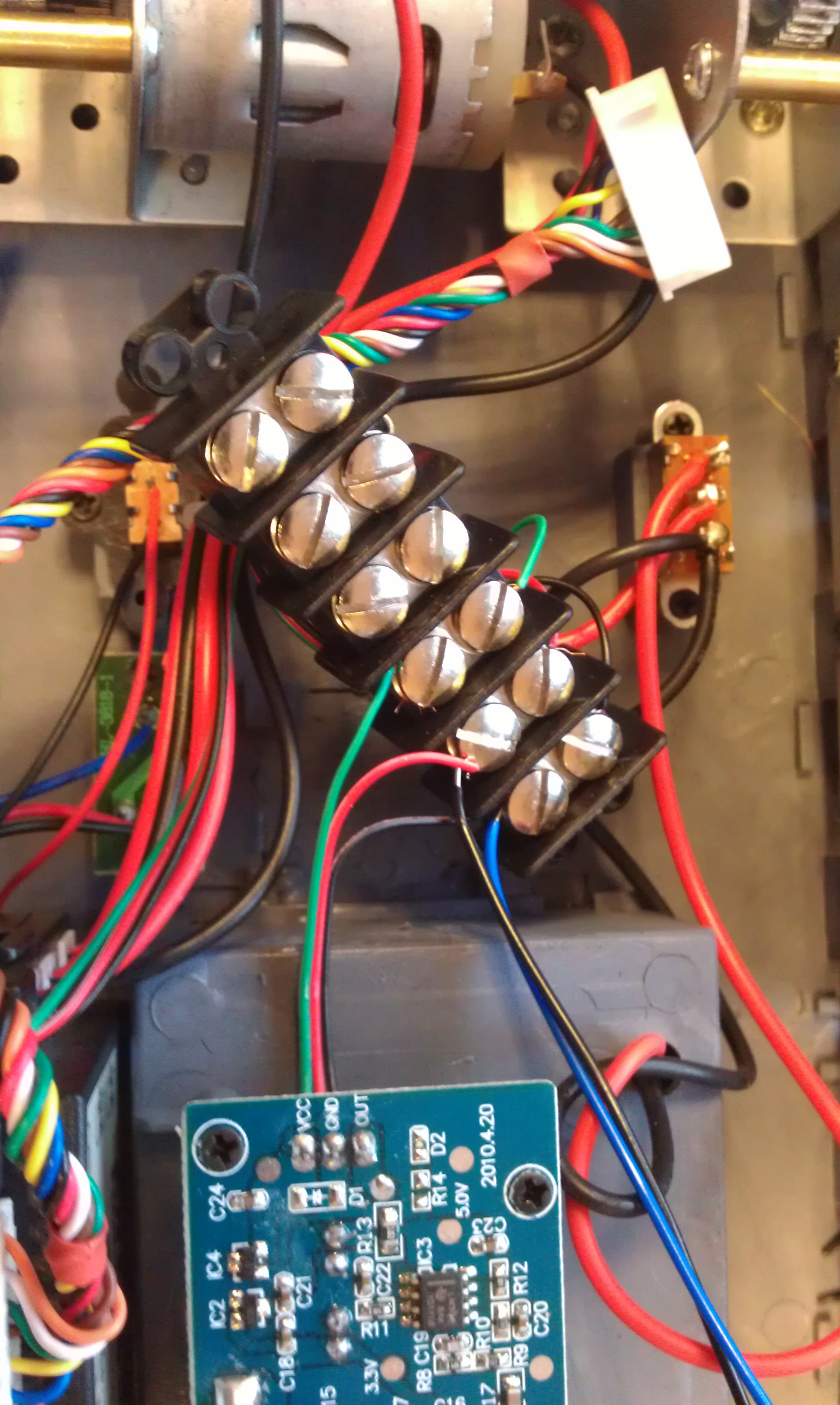
I found an old bit of choc block (not the tasty kind) lying around, and split that red, black and green cable from yesterday with that in the middle. Trailing leads were attached to the signal and ground lines (oddly coloured black and red respectively) and plugged into the only oscilloscope I had handy.
Step 2: Sampling the Signal
A bit of manual triggering revealed the approximate nature of the command signal, and verified that it changed slightly when the remote controls were altered, but unfortunately the scope was not advanced enough to reliably trigger on the beginning of each message, meaning that it was impossible to watch the waveform change with the remote controls in any sensible way.
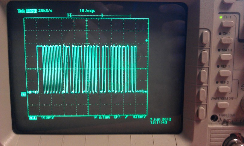
The signal was 20ms long, with a 4ms gap between each. Within the signal itself, there were oscillations between 4V and 0V with the shortest mark or space taking around 300 microseconds. The first 5ms or so of the signal were roughly constant, but that was as far as I got.
I set off to find a proper logic analyser and returned… to discover that the internet had done the work for me!
Step 3: Cracking the Code
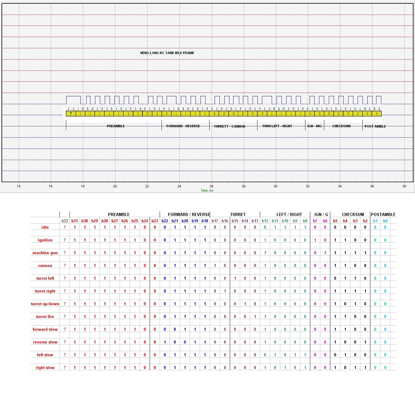
While I was trying to track down a logic analyser, ancvi_pIII on the RC Tanks Australia forum posted exactly the waveform I was looking at – explaining that it was a Manchester coded bit pattern, and listing all the currently-known commands that it can send.
Reverse engineering is easy when other people do it for you :)
(In case that forum disappears from the ‘net, the relevant image is here. All thanks to ancvi_pIII for producing this!)
Now, there remains the slight issue that we have not yet figured out the checksum algorithm employed by the TK-YL101 chip. I have had a go at looking for patterns, and checked the results of a 4-bit XOR and various 4-bit sections of an 8-bit XOR, but so far have achieved nothing besides increasing my respect for Alan Turing.
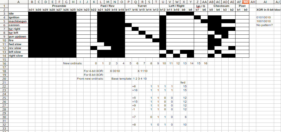
Still, even without the checksum algorithm we still have 12 command sequences that can control each function of the tank – all we are missing is the ability to use them in combination, which may be an issue for hobbyists improving their remote controls, but is less so for an autonomous vehicle where time and fluidity of motion are rarely paramount.
So what’s next?
While I continue to have a go at the checksum code in the background, the Raspberry Tank project can move forward with what we already know. Next time on the Raspberry Tank build diary, we will get a program up and running on the Pi to see if its GPIO pins will be able to recreate the TK-YL101 board’s signal!
Comments
This is amazing stuff tank captain. Very instructive. Job well done and Thank you!