Today, we continue the list from day 21 of things to do that would make the Raspberry Tank fully autonomous. Last time around we played with software – now it’s time to get the soldering iron out.
Step 1: Choose Sensors
Two sensors were chosen for the Raspberry Tank’s first foray into detecting its environment: An ultrasound rangefinder (SRF02) and a 3-axis compass (CMPS10), both ordered from robot-electronics.co.uk. Beyond their I2C interface, these devices were chosen largely for cost reasons, though they should both be fine for the job they will have to do on the tank.
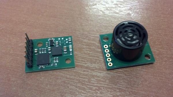
Compass Module and Ultrasound Ranger Module
Step 2: GPIO Breakout!
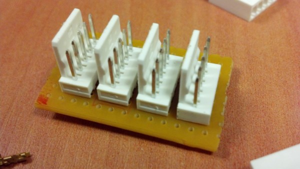
Way back on day 7, we attached a simple connector to the Raspberry Pi’s GPIO pins in order to extract GPIO 7 and Ground to feed into the tank’s motor control board. Now we need three more connections onto the GPIO header - for 5V, I2C Data (SDA) and I2C Clock (SCL). Several of these pins must now be connected to more than one device, to to avoid some very messy connections, I constructed a simple break-out board for the GPIO connector.
This allowed the two I2C devices to be connected in a slightly neater way.
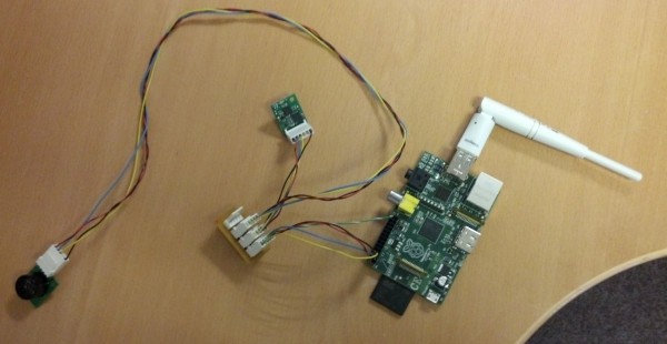
Rangefinder and Compass Connected to Raspberry Pi
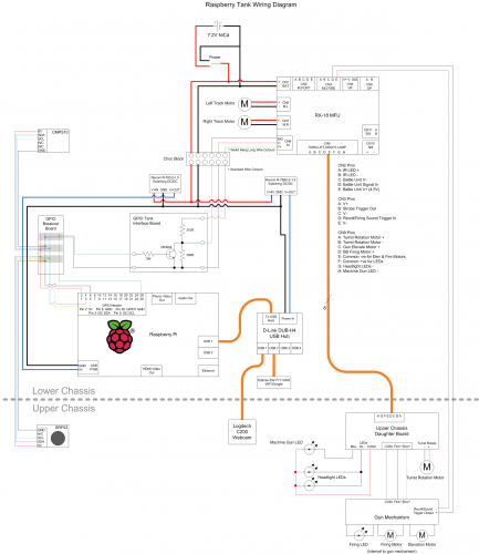
The Raspberry Tank electrical schematic now looks like this:
You can download that as an SVG file here: Raspberry Tank Schematic (Day 23)
Step 3: Testing
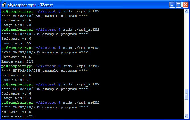
Handily, the guys at robot-electronics.co.uk have already produced sample programs to read the data from their devices on a Raspberry Pi, which work perfectly under Occidentalis. These had to be run as root to have access to the virtual I2C device, /dev/i2c-0.
These were loaded onto the Raspberry Pi, compiled, and run. The results were… pretty good!
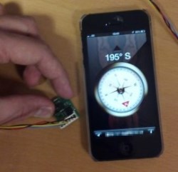
The compass module’s “forward” direction was determined to be towards the header pins, meaning that if this edge was pointing north, the compass module returned a bearing of roughly zero degrees. This was compared against the compass reading provided by a nearby iPhone, and was found to be accurate to around 10 degrees – not perfect, but acceptable.
The rangefinder was also tested at a variety of ranges, revealing a minimum range of around 20cm and a maximum range of around 3m. It was also found that spuriously high or low readings (e.g. 250cm and 0cm for a real distance of 50cm) were sometimes reported, so some degree of sanitisation will have to be applied to the data returned by this sensor.
Step 4: Mounting
With the sensors tested, all that remained was to mount them (and remount the Raspberry Pi) inside the tank.
As a magnetically sensitive device, the logical position for the compass module was at the rear of the tank, as far as possible from the magnetically noisy motors:
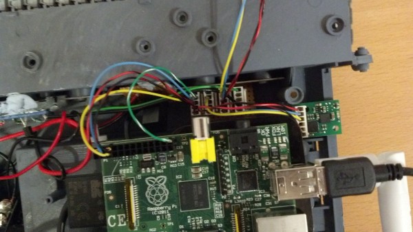
Rear Electronics, showing RPi, GPIO Break-out and Compass
And the logical place for the rangefinder is, of course, the front:
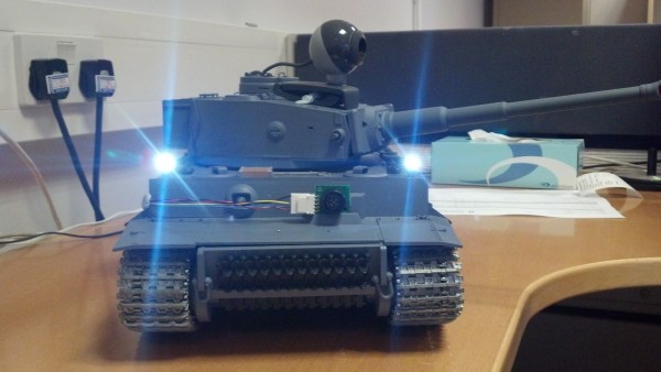
Front Mounting for Rangefinder
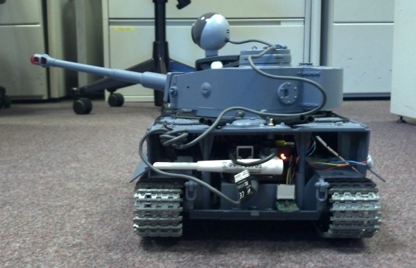
And with that, office warfare was ready to commence again!
Of course, although we now have a working remote control system and working sensors, the two aren’t yet combined. Next time on the Raspberry Tank build diary, the new sensor code will be integrated into the existing remote control software – a step closer to autonomy!

Add a Comment