Last time around, we proved that the Raspberry Pi could indeed be integrated into a Heng Long Tiger I RC tank, and so control its functions. That’s a significant achievement, but there’s plenty more to do.
Firstly and most importantly, we can’t yet drive the tank around because the Raspberry Pi is still dependent on a power source, keyboard input and video output – each of which is a cable connecting the tank to a computer. On day nine of the build diary, we cut one of those dependencies, resulting in a Raspberry Pi that is powered from the tank’s internal battery. Compared to previous days, this was a relatively simple matter.
The tank’s power supply comes from a 7.2V NiCd battery. The Pi’s power input is a very strict 5V ±5%, so we sourced a component that could convert one to the other. The Pi’s maximum current draw of around 1A was also a consideration. A cheap voltage regulator such as the ubiquitous LM7805 could do the job, but it would need protective capacitors in parallel with it, and would also give us a heat dissipation problem – the regulator would get rather hot stepping 7.2V down to 5V at 1A, and the plastic body of the tank gives us no convenient heat sinks.
Instead of a regulator, a switching DC/DC converter was chosen, specifically a Recom R-785.0-1.0. This provides exactly the voltage and current output we need, with a higher efficiency so less heat dissipation. The tank’s 7.2V battery is well within its input range, even accounting for possible voltage drops when the battery charge is low.
This component was bought and soldered to a small piece of veroboard, with flying leads to connect to the tank’s power supply (via our choc block) and a hacked-up microUSB cable to connect to the Raspberry Pi. (The USB cable I chose to cut up had the normal red, black, green and white cores as expected, but the black core was just a strain member – full of fluff – whilst the ground line was actually connected to the screen. I’m not sure how common this is, so watch out for it if you are recreating this build.)
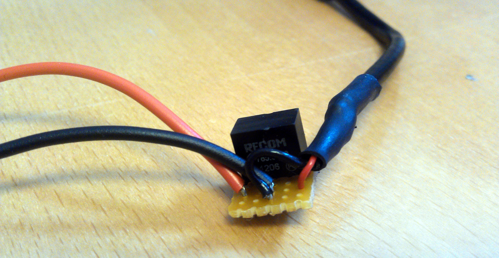
Raychem hides many sins.
Once built, this board was tested with a power supply providing the 7.2V and a multimeter checking the 5V output. Once I was happy that the output was clean and at the right voltage, the Raspberry Pi itself was connected and booted up. During the boot process, the current draw on the 7.2A side peaked at 550mA, coming to stabilise at around 250mA once the Pi was idle.
(Warning to anyone recreating this build: Please use a bench power supply at this stage, don’t go straight for the tank’s battery as a power source. Dodgy wiring or soldering could short the battery, leaving you with an exploded mess where your tank once was.)
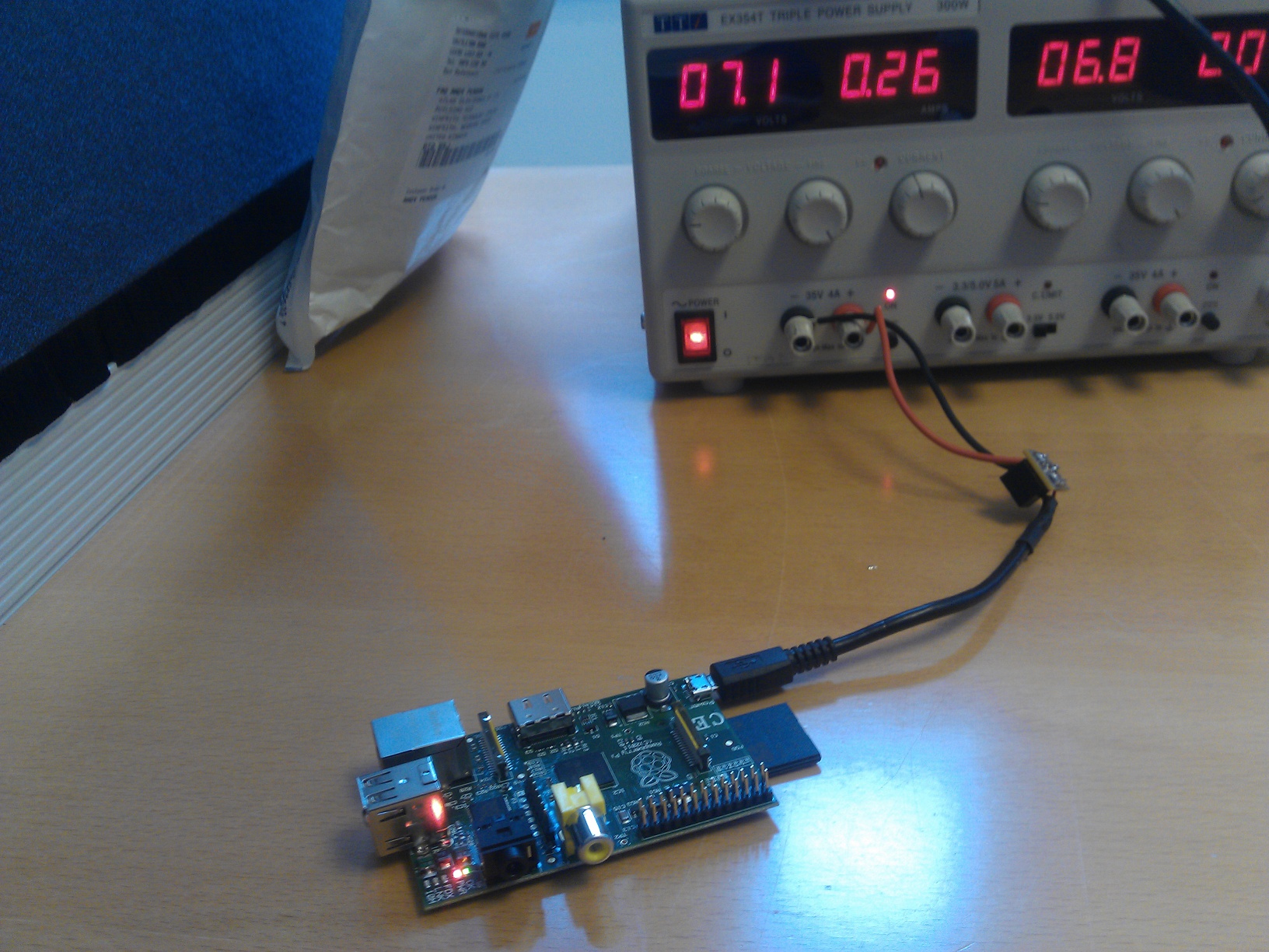
Once I was sure that the power supply to the Raspberry Pi was working correctly, we then switched out the bench power supply for the tank’s battery. And voila – we now have the tank powering the Pi as well as itself.
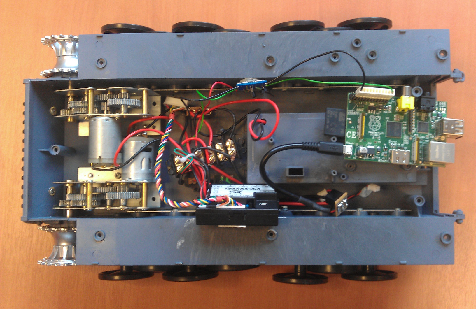
With the upper chassis removed, the tank now looks like this:
In case you’ve lost track over the last few days of the build diary, the electrical schematic now looks like this (including the upper chassis):
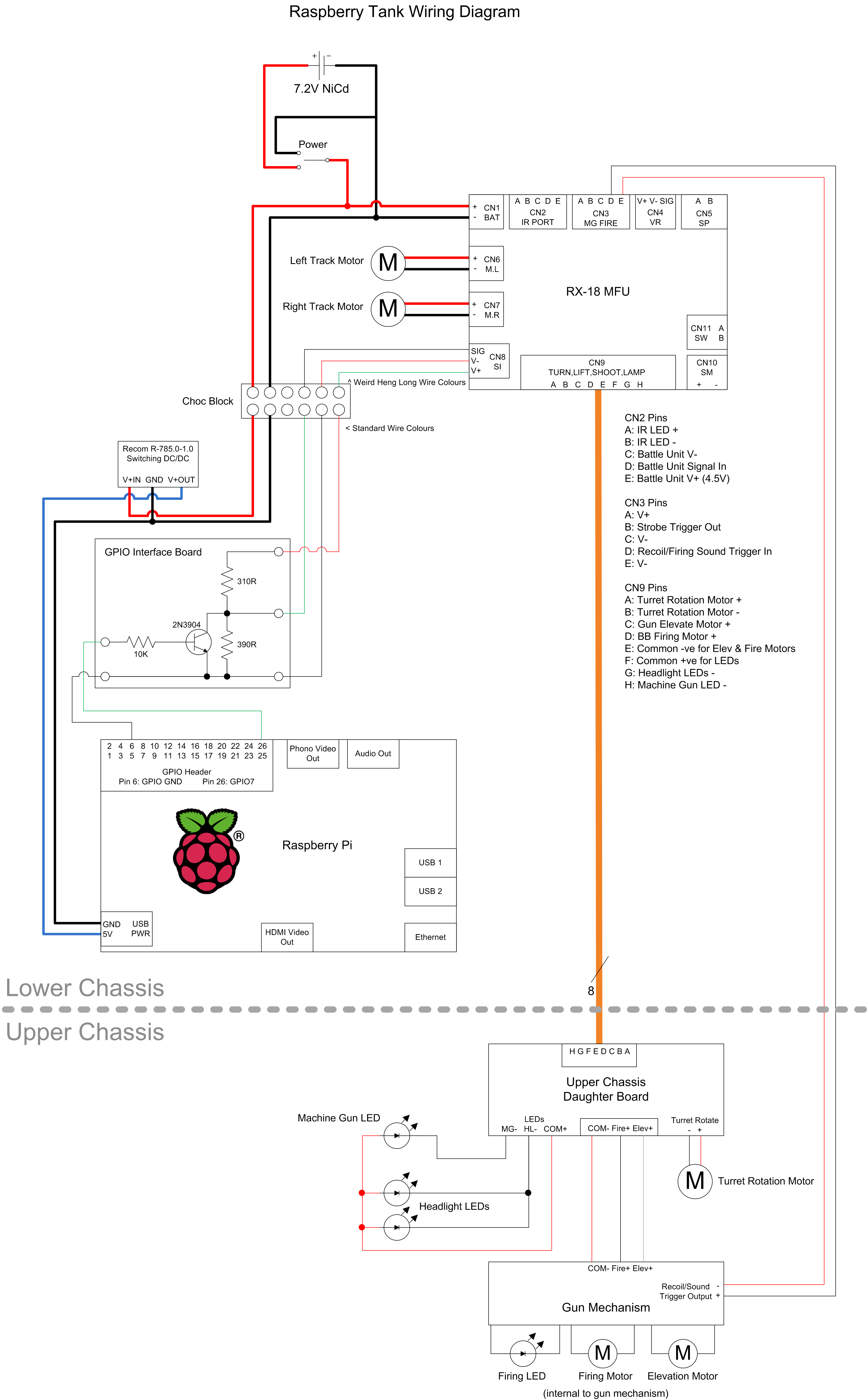
You can download that as an SVG file here: Raspberry Tank Schematic (Day 9)
Next time on the Raspberry Tank build diary, we will be integrating a WiFi dongle into the tank and enabling SSH on the Raspberry Pi in order to remove the last two cables keeping the tank from roaming freely.
Comments
You can used Pin 2 from RPI-Header for +5V power supply, instead of the USB.
Pin 4 is also GND (the other DNC Pins are GND too)
Kirsch: I did think about doing that, but drawing current from the 5V GPIO pin reduces the amount of current available to the Pi's USB devices. (http://elinux.org/Rpi_Low-level_peripherals#Power_pins) Since I wanted to attach a WiFi dongle and a webcam to the USB ports, I figured I'd leave as much potential current spare as possible by drawing straight off the tank's main battery here.
I'm trying (in theory - my RPi is still in the mail) to use the same 7.2V battery pack for an RC car DC motor and a RPi. Are any components required to split the battery between the motor and the converter? Can I just fork the +/- wires coming from the battery or do I need diodes or something (sorry, I'm quite new to electronics)?
Also, what is your battery's capacity and how long does it last?
As my circuit diagram shows, the only component between the battery and the DCDC converter in the tank is the main power switch. (It's a good idea to include a switch as the DCDC converter will draw some current from the battery even if the Pi is off.
If I were powering something other than a computer from the 5V supply I'd be tempted to protect the DCDC with some diodes, but the Pi isn't going to generate any significant back EMF or anything, so you should be fine if you're using the same model of DCDC as me. Other converters might be more picky -- usually the datasheet will show you how to use diodes if necessary. (<a 0="" href="http://uk.rs-online.com/web/p/dc-dc-converters/6727124/?searchTerm=672-7124&relevancy-data=636F3D3126696E3D4931384E525353746F636B4E756D6265724D504E266C753D656E266D6D3D6D61746368616C6C26706D3D5E5C647B337D5B5C732D2F255C2E5D5C647B332C347D2426706F3D313426736E3D592673743D52535F53544F434B5F4E554D424552267573743D3637322D373132342677633D4E4F4E4526" rel="nofollow noopener">http://uk.rs-online.com/web/p/dc-dc-converters/6727124/?searchTerm=672-7124&relevancy-data=636F3D3126696E3D4931384E525353746F636B4E756D6265724D504E266C753D656E266D6D3D6D61746368616C6C26706D3D5E5C647B337D5B5C732D2F255C2E5D5C647B332C347D2426706F3D313426736E3D592673743D52535F53544F434B5F4E554D424552267573743D3637322D373132342677633D4E4F4E4526</a>" rel="nofollow">Here's the datasheet for the DCDC I used.</a> Optional protection circuits are shown on page 2.)
My battery is 1700mAh. I've never tried powering the Pi on its own, but the Pi draws around 250mA from the 7.2 side when powered up and idle, so that probably equates to around 6 hours. When moving, shooting etc. the tank lasts about 30 minutes on a charge. I'm planning to upgrade to 3000mAh LiPo batteries at some point!
Ok, thanks. Sounds like a 3000mAh battery should suffice in my case.
Hi, this looks like a great project and as soon as my tank arrives I will begin. I just had a quick question, could you not just power the raspberry pi from some AA batteries? This would also let the tank run for longer
Absolutely. I chose to power mine from the tank's main battery for a couple of reasons: firstly so I would only have to remember to charge one battery pack, and secondly because internal space -- particularly at the more accessible rear of the tank -- is limited.
However, the RPi, Wifi dingle and webcam are a constant 1.5A draw on the battery, which in my experience reduces run time by around 30%.
If you're interested in running your RPi from AA batteries, you may need a voltage regulator (depending on the type of batteries you use). This StackExchange question and the pages linked from there are a pretty good summary of how people are doing it: http://raspberrypi.stackexchange.com/questions/35/what-do-i-need-to-know-to-power-from-batteries
Bear in mind that, just the same as when using the tank's main battery, the RPi will brown-out without warning when the battery voltage drops below 5v.
Thanks
Hi Guys,
Check out BattPi - BattPi is a Case for Raspberry Pi with integrated Battery and Real Time Clock. Built in UPS offering up to 8 hours of battery life.
https://www.kickstarter.com/projects/719364198/raspberry-pi-case-with-real-time-clock-battery-and?ref=nav_search
Thanks,
Shahid Darbar
Great article. Thank you, Ian.