If you’re following along with this build guide and have a particularly keen eye, you may have noticed a small 7-year jump in date between the previous post and this one. Yes, after a long time sat unloved in the shed (the boat, not me) I’ve finally developed some enthusiasm for the project again.
Back in 2016, the Harry Paye was using an original Raspberry Pi Model B, a servo control board made by some guy on the internet, USB serial converters, a USB WiFi dongle, etc.—it was pretty chunky compared to the small amount of space available inside the boat:
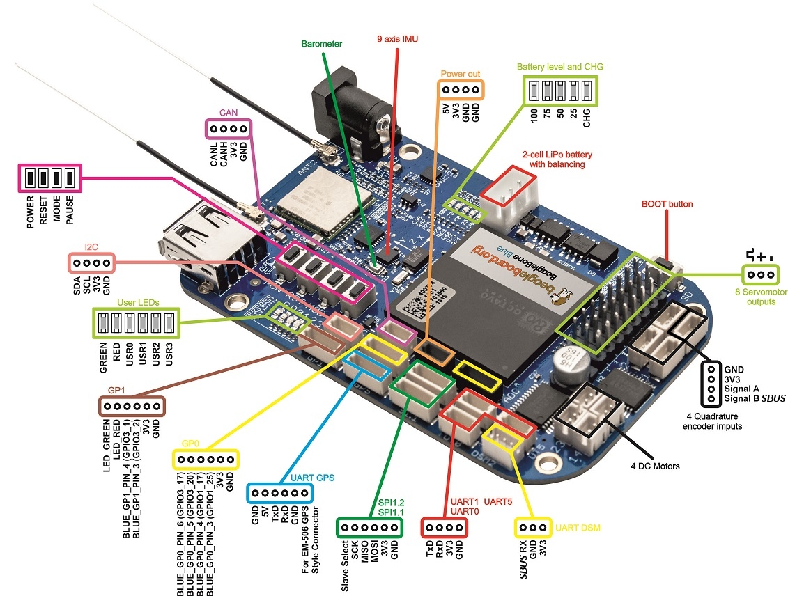
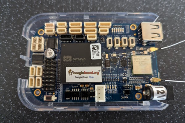
Since then, hobby robotics boards have come on a long way. (Now Ardupilots did exist back in 2016 and were fine for some simple boat driving, but I did want a “proper” PC with WiFi to be at the heart of this system, hence the Pi and all its chunky accessories.) One of my favourites is the Beaglebone Blue, which has built-in WiFi, battery regulator, PWM servo control and a 9DOF MPU, along with standardised connectors for things like a GPS. Pretty much everything you could want, really:
So, I decided to redesign the internals of the Harry Paye around the Beaglebone Blue.
Recovering the System
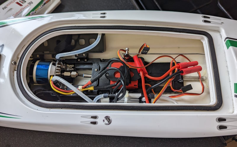
Despite several years exposed to the conditions inside my leaky shed, the internals of the boat seemed pretty much fine:
Only the batteries were a problem; they had swollen slightly, and not willing to trust the safety of the model to two Chinese spicy pillows, I ordered some new ones.
Electronics & Mounting
It turns out that there just aren’t any cases for the Beaglebone Blue out there—at one point there was one, but they’re now impossible to get hold of. For the initial prototype of the redesign, I bought a case for the Beaglebone Black (of which there are many) and cut holes out of it to suit. (However, if you’re following along at home, you may want to skip this step as I later found it almost impossible to fit the Beaglebone into the boat with the case on, and eventually removed it.)
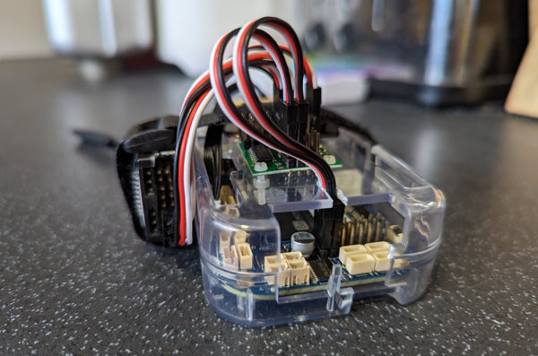
At least the board still fitted neatly in the lower half of the case:
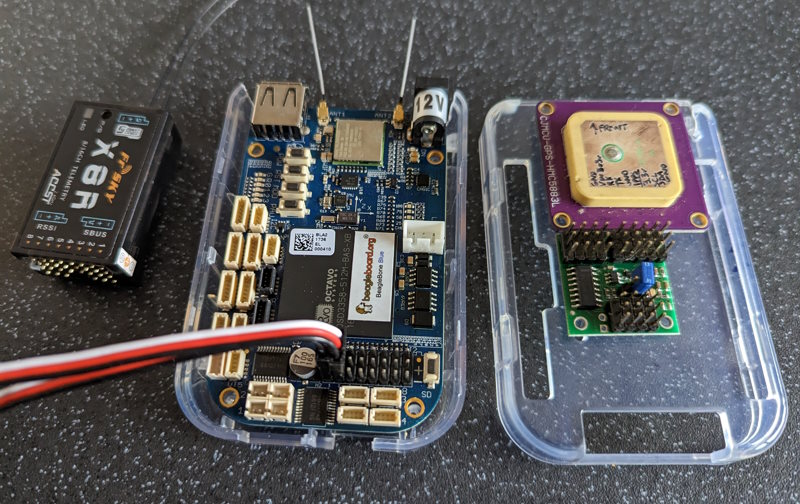
I wanted to re-use the GPS, the servo multiplever board and the handheld controller receiver from the version 1 build, and attach them into a neat package—or at least, as neat as I could manage without putting more than half an hour’s effort into, for now.
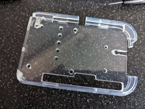
A few extra holes and cut-outs were required in the top part of the case:
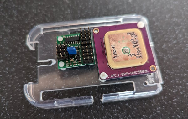
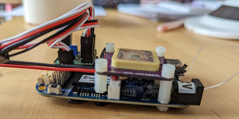
The GPS and servo multiplexer were attached with 3mm and 2mm nylon bolts:
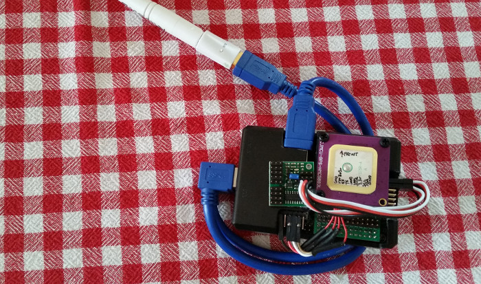
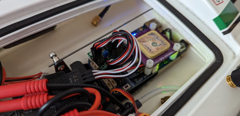
It looks like it’s all going to come together neatly, until you remember to add the cables:
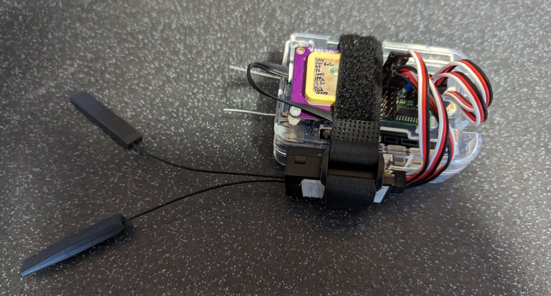
As mentioned above, I really struggled to fit the electronics assembly inside the boat, so eventually decided to give up on the case and mount the extra boards directly to the Beaglebone board using PCB spacers. Unfortunately the spacing of the holes doesn’t lend itself to this, but this is what I ended up with:
The servo multiplexer board had some protruding solder joints on the bottom that got very close to some pins on the Beaglebone, so I covered the bottom with electrical tape for good measure.
Without the bulky case, the board now fits much easier in the stern compartment of the boat. It remains to be seen if it gets wet in there, of course…
Improving the WiFi
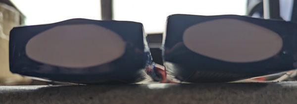
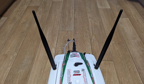
Those two little wires you may have noticed protruding from one end of the board are the WiFi antennas. It is two-channel MIMO, but while their performance is fine for communicating with the device at close range, out on the water will be a different story. I removed them from the U.FL connectors on the board and attached external antennas outside the hull.
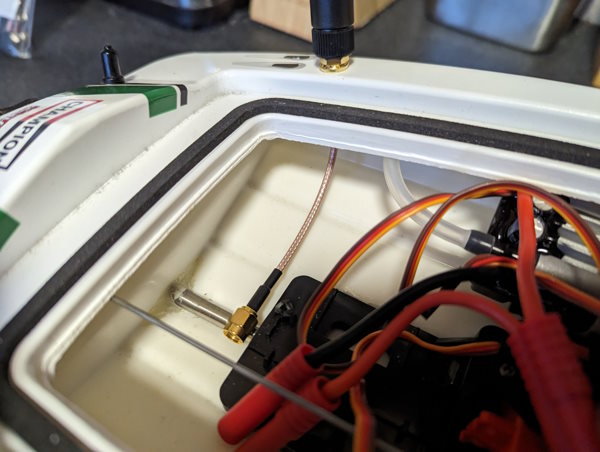
I chose SMA-to-SMA for the through-hull part, then a separate SMA to U.FL to attach to the board. This allows the through-hull connector to be glued in place to prevent water ingress, but still allows the Beaglebone to be removed without having to detach U.FL connectors, as these are designed for only a small number of mating cycles.
Replacing the U.FL pigtails with new U.FL-to-SMA cables was probably the most fiddly part of the build. U.FL is just the worst.
The GPS Re-wire
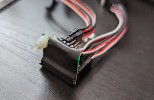
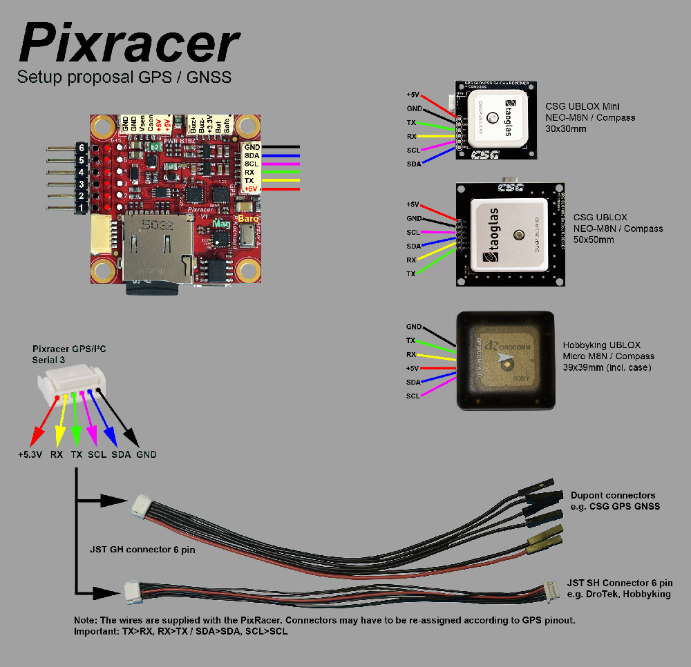
The good news about GPS receivers for hobby robotics projects is that many of them use the same connector, a 6-pin JST with 1mm pitch spacing. The bad news is that the pins in that connector are not always in the same order…
I had to reverse the pin order to get my CJMCU uBlox M8 GPS working with the Beaglebone Blue. Not the end of the world, but a very fiddly job requiring a tiny screwdriver to release the plastic catches.
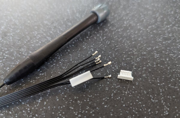
You can of course buy pre-crimped lengths of cable and empty connectors, which are almost more common than the pre-made cables—almost as if this was a common problem!
Note that with only microUSB power connected, the Beaglebone Blue does not power up the +5V output on this connector (or the 6v power line for servomotors). It’s only enabled when a separate power source is connected via the barrel jack or battery balance connector.
The Servo Multiplexer
As before, I’m using a servo multiplexer board between the RC receiver & Beaglebone on one side, and the throttle ESC & rudder servo on the other. This allows me to select which of the two inputs gets through to the outputs, using a multiplexer driven by the RC receiver.
This means that I can set up one of the shoulder switches on my transmitter to swap between driving the boat direct from that transmitter, and listening to the Beaglebone.
I can therefore easily swap the boat back into “fun mode” if required, and in particular if something goes wrong with the software, I’ve got that as a fallback control method.
Finishing Off
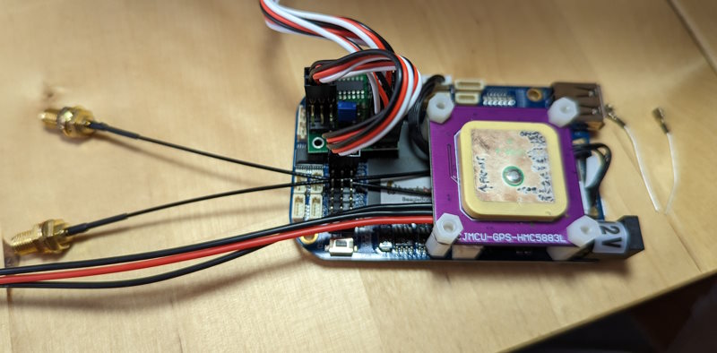
The completed electronics build now looks like this:
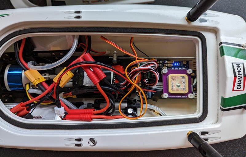
A horrible mess, but we can work on that with some better cable routing & tidying.
As you can see, the Beaglebone is now powered from the boat’s batteries using the battery balance connector. This allows the GPS and servo outputs to power up, and we can get on with the software side of the build.
Add a Comment