“Plane/Sailing Portable” is a tiny hardware stack designed to be installed in ad-hoc locations, fitted to a vehicle or even carried in a pocket, from where it can contribute ADS-B, AIS or APRS coverage to the Plane/Sailing tracking system.
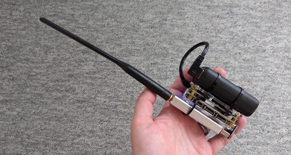 The second prototype of Plane/Sailing Portable, held in hand
The build guide is split into sections on the following pages.
The project is still at the prototype stage (cable ties are still involved!)—see the final page for potential future improvements to be made.
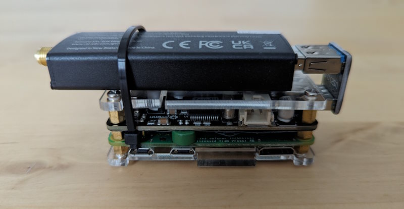 Close-up of the second prototype of Plane/Sailing Portable
Add a Comment