With a pi, three RTL-SDRs, a separate pre-amp for AIS and miscellaneous other clutter on my desk, it’s no surprise that the Plane/Sailing build was getting rather messy…
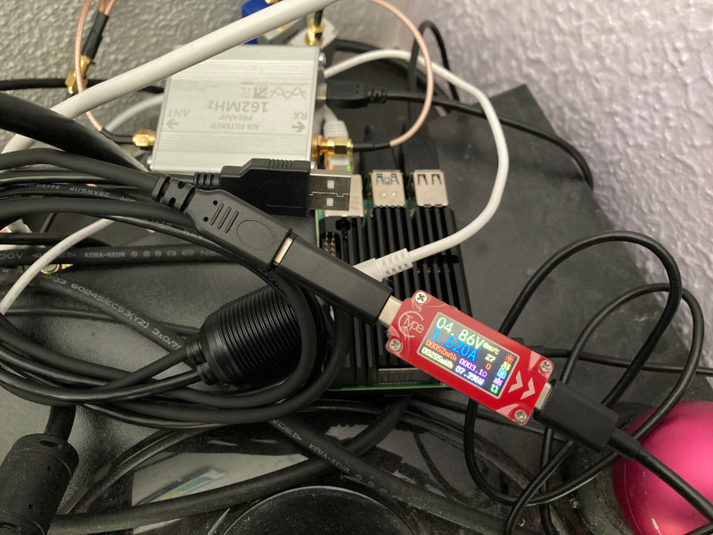
As well as just looking bad, the SDRs had a minor overheating problem, with them all packed close together, and also a stability problem—an accidental wobble on an antenna cable meant loss of USB connectivity, from which the connected application does not always recover.
I have updated the bill of materials with a list of the components used to build an enclosure for the project that will keep it neat and tidy, plus offer some extra heat sinking capability for the Pi and SDRs.
Note: Since building Plane/Sailing into my enclosure, I have noticed occasional drop-outs of one of the RTL-SDRs, after a few days of running. I initially thought this was a temperature problem, but I now believe it's power—the Pi's USB ports just don't seem to have enough juice for all three dongles, even with the 4A USB-C supply that I use. Your mileage may vary, so I would recommend soak testing your setup for at least a couple of weeks to determine its stability before committing to a certain build. (I ended up having to separately power the USB hub, but if you're going down that route please note the very important warning on the product page about opening the case and cutting the white wire before doing so!)
Build Steps
My first step was to use some “CAD” (Crayon Aided Design) to decide on a suitable enclosure.
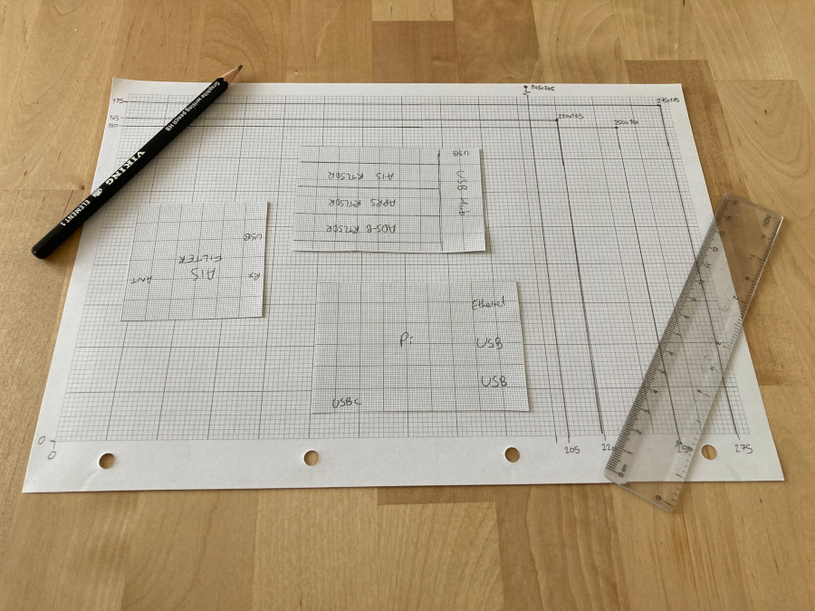
I ended up purchasing a 5cm-high Eurocard enclosure which neatly fits the Raspberry Pi, USB hub and SDR dongles without taking up too much desk space. However, it’s very fiddly to mount components inside as the top doesn’t come off! Although this choice allows for the smallest amount of desk space taken up, if I expand the project in future I will probably look at something more like a 19-inch rack enclosure which will allow much easier access to components. See the bottom of this page for more information.
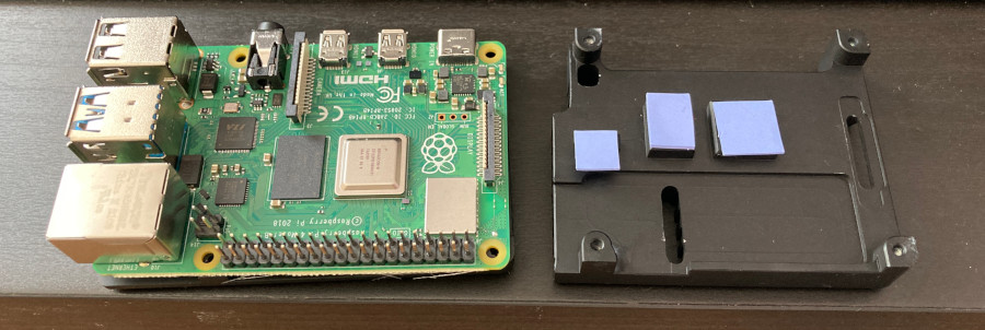
In order to improve heat dissipation, I mounted the Pi in a metal “heat sink” case that should allow more heat to be transferred to the main enclosure than a normal Pi case would. (This case is actually visible already in the photo at the top of the page). It comes with small adhesive pads to thermally connect the major components on the board to the metal heat sink, and I used additional adhesive thermal tape to bond the case to the bottom of the enclosure.
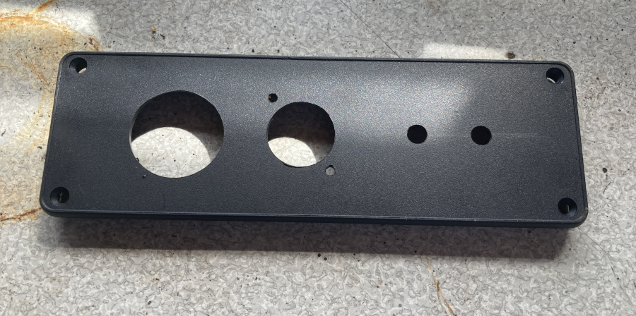
I decided that all connections should go in through the back of the enclosure through the removable plastic panel to keep things neat and tidy. The SMA connectors were simple enough to drill holes for at 6.5mm:
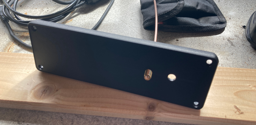
The USB socket (26mm) and Ethernet socket (22mm) were a little more difficult and required the use of a stepped drill bit to achieve the right size:
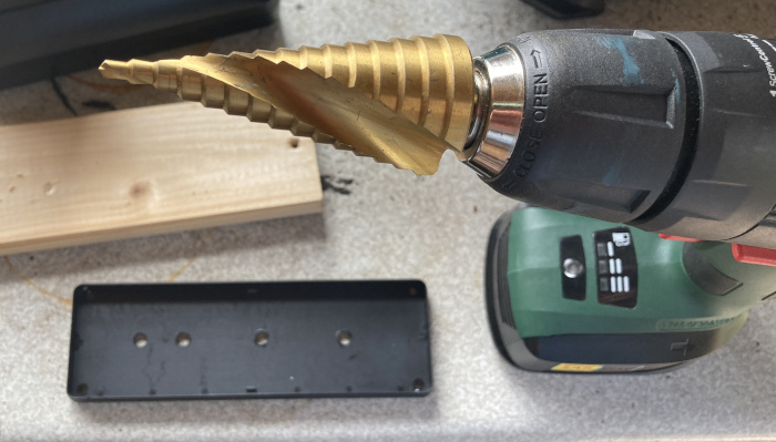
Extra 3mm holes for securing the Ethernet socket finished the job.
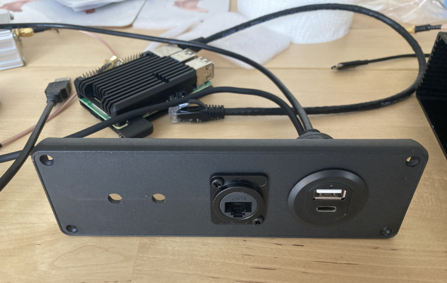
The USB and Ethernet sockets fitted neatly into the holes:
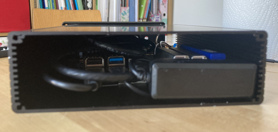
Unfortunately the cables on the back of the USB socket are a bit long, so the inside of the box is already going to look messy:
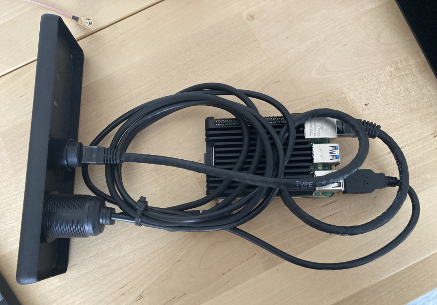
Ideally I wanted the USB C panel mount socket to be a socket on both sides so I could provide my own shorter cable, but unfortunately I couldn’t find any products like that for sale. In a future build I may chop the internal USB cables to length myself.
With the USB hub and SDRs inside, the box is a snug fit - much more so than the “CAD” indicated at first glance. There was definitely not room for the AIS pre-amp. It’s also pretty messy in there; as previously mentioned the lid of this box isn’t removable so aligning the components was a case of putting things in roughly the right spot then hoping it’s lined up as you press down on the sticky heat-conductive tape. I’m pretty sure the Pi is actually at a weird angle.
Nevertheless, once it’s all boxed up it looks neat from the outside, no matter what it might look like inside.
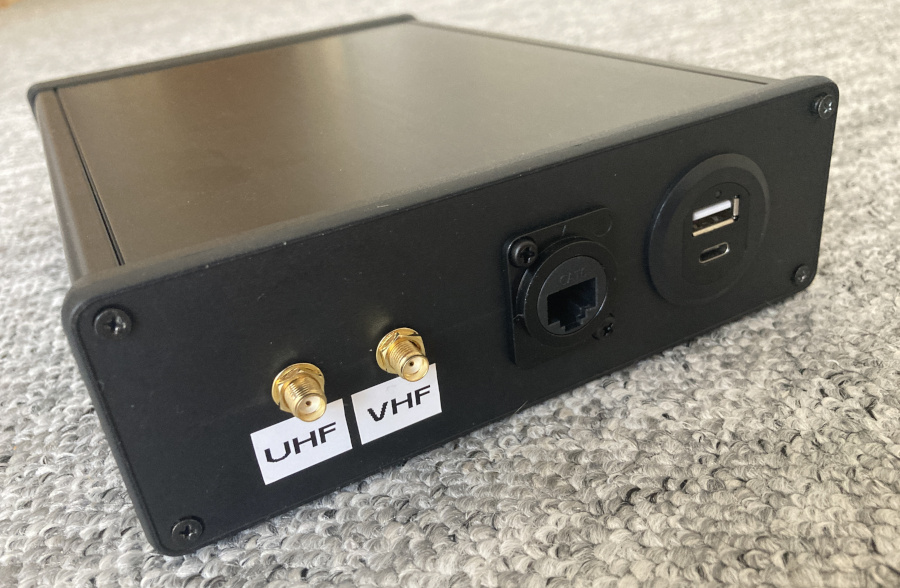
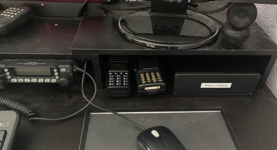
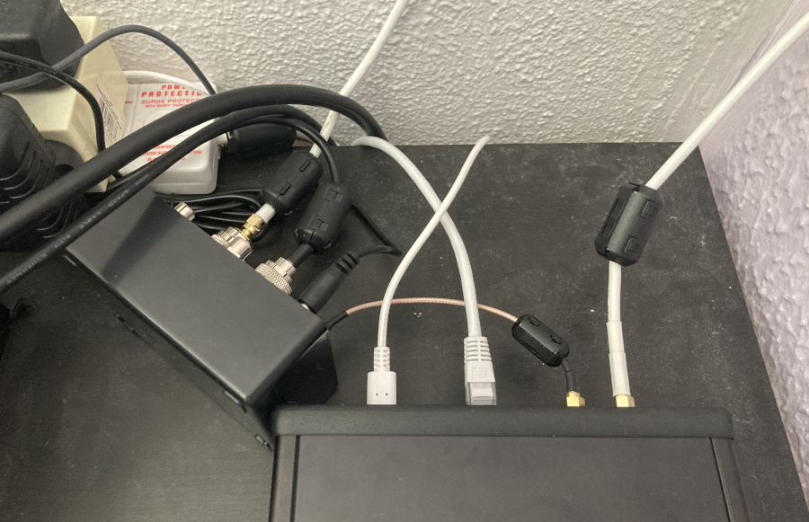
The Plane/Sailing enclosure now sits neatly on my desk, looking like a simple “black box” from the front, and significantly tidying the mess of cables I used to have at the back.
Future Plans
As mentioned above, if I choose to redo this aspect of the project, I will use a much larger case with a removable top so that I can do the internal layout much more neatly. I am considering using a 19-inch rack mount size box, 2U or even 4U, so that I have plenty of space and access to it. With the extra space available I may make it a general “radio electronics box” rather than it being Plane/Sailing specific, so I can include other “messy” components like my antenna switcher inside it and include a mains splitter too. A fully metal case would help with EMC as well—the Eurocard enclosure has plastic ends which are nice and easy to drill but no help in isolating the sensitive SDRs from any stray RF that might be around.
At that point I will likely include the AIS filtered pre-amp as a permanent part of the build. I considered adding the USB current/temperature meter shown on the Raspberry Pi page as a permanent part of the build too, with a rectangluar window cut in the front panel so that it can be viewed. However, since the current is fairly constant and the mostly-metal enclosure is already helping a great deal with temperature, I think that’s overkill, so I will reserve that as part of my test kit for future projects. However, in an updated enclosure I may add panel-mount LEDs, one for Raspberry Pi power and maybe three additional ones that flash on ADS-B, AIS and APRS packet reception.
Add a Comment