Yesterday, we finished up with a Raspberry Pi which could output the appropriate command signal on one of its GPIO ports, but we had concerns about the output voltage level. At 3.3 volts, this is lower than the 4V input that the main controller board is used to seeing from the TK-YL101-3 board that we intend to replace.
Following the general theme of advice on the Raspberry Pi forums, I decided to add a transistor circuit between the Pi and the tank to prevent excess current draw from the GPIO pin, which can damage the device. While doing so, it costs nothing to bump that 3.3V output up to the expected 4V – so we did. Rather than using the 4.5V output from the RX-18, we decided to use the 7.2V power line that previously powered the TK board. This meant that we could use just the three wires that connect the RX and TK boards, rather than taking power from somewhere else.
This is the circuit we designed (100% of the credit going to my colleague Daryl, as I appear to have forgotten everything I learned in A-level electronics):
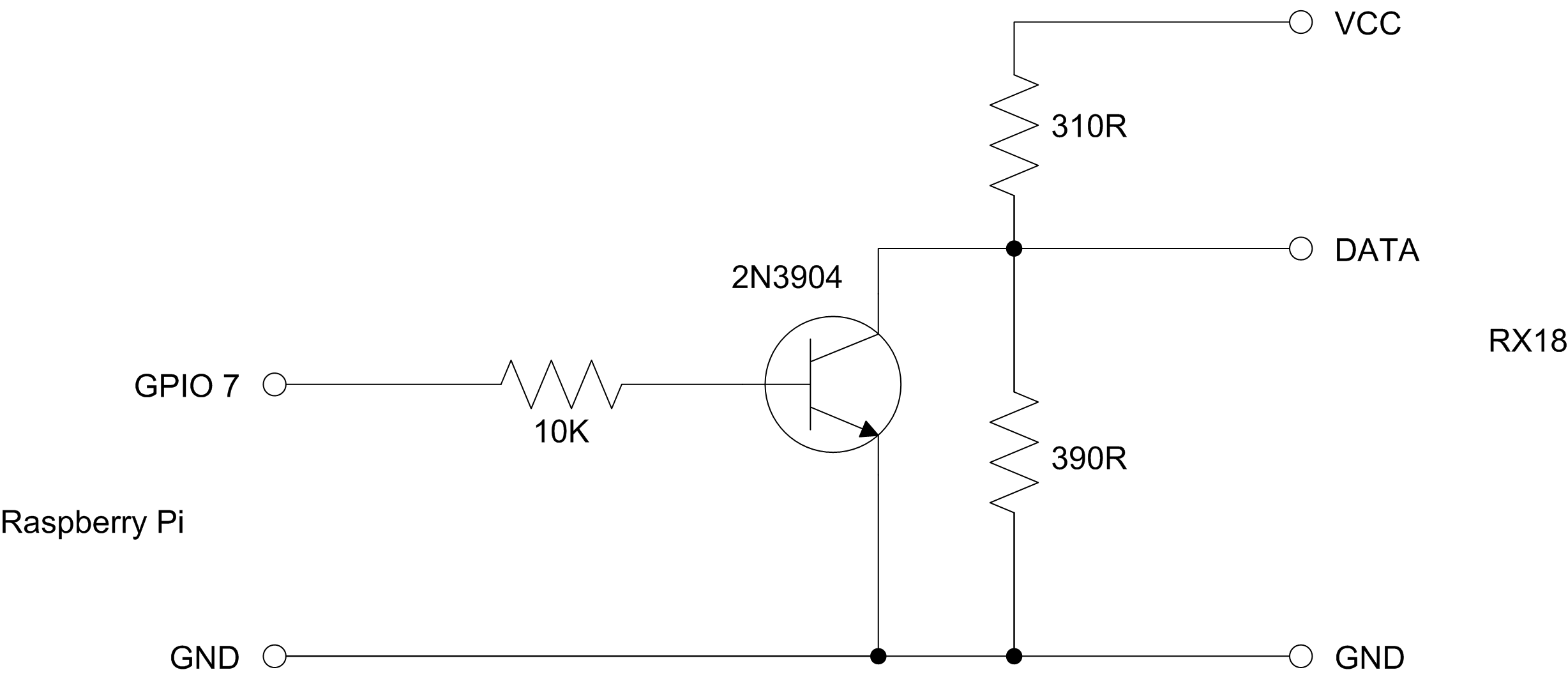
The 2N3904 transistor has a high enough slew rate and hfe that we can choose a relatively high value for the resistor between the GPIO pin and the transistor – in this case, 10K. This really cuts down on the current being drawn from the GPIO pin, protecting the Raspberry Pi. On the other side of the transistor, a potential divider created with the 310R and 390R resistors creates a 4V level from the 7.2V power line.
Without further ado, I built the circuit on a scavenged bit of stripboard:
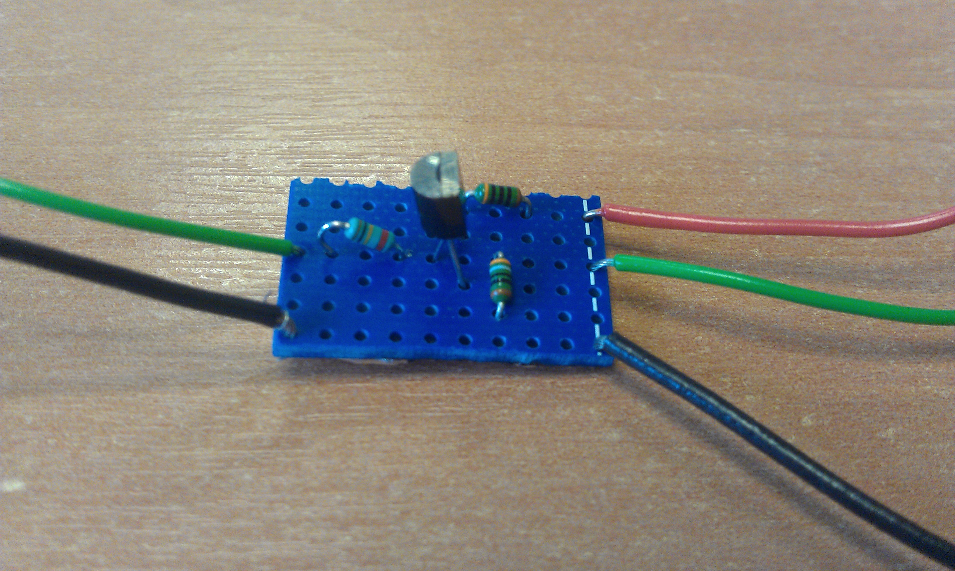
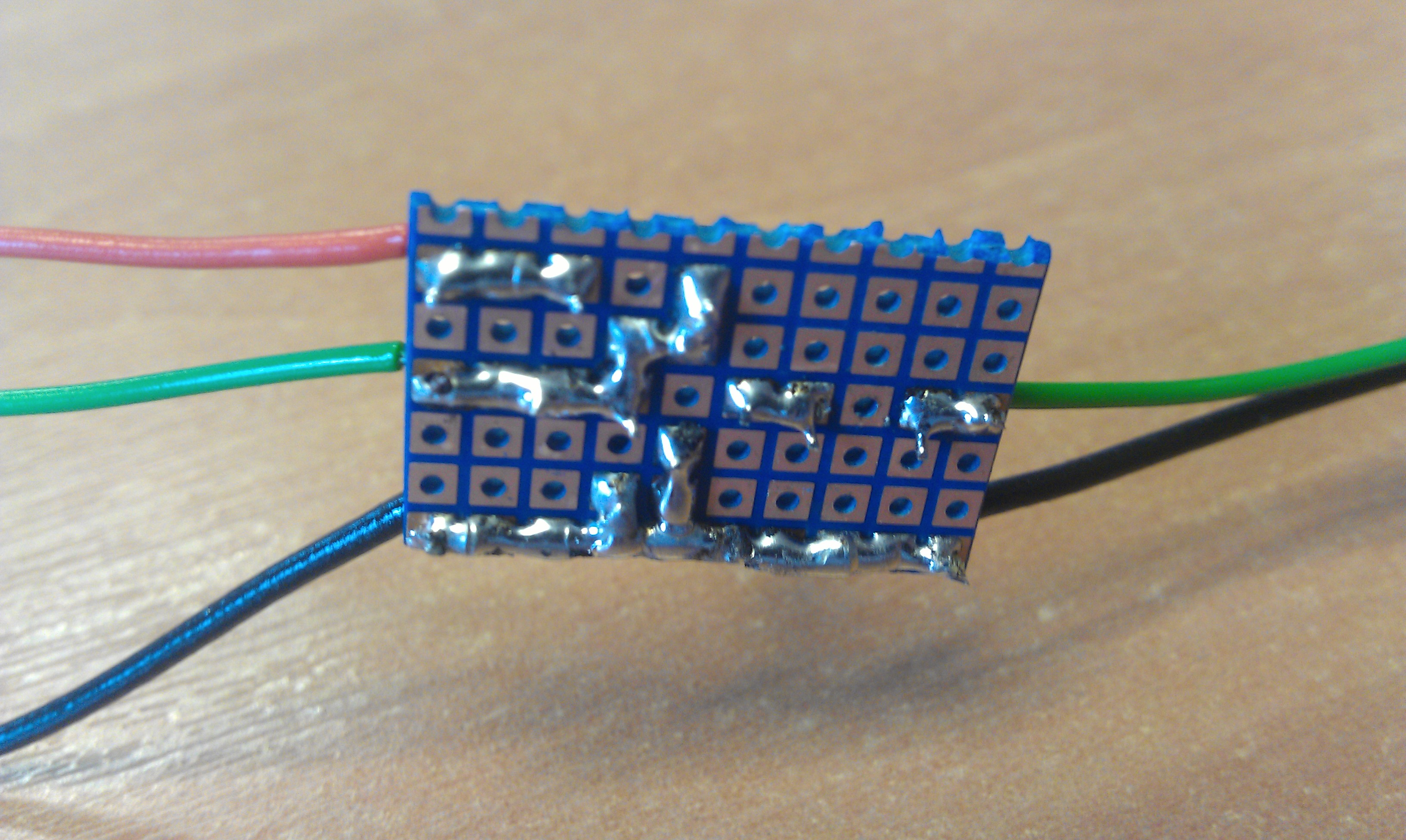
Believe it or not, that’s probably my best-ever solder job. There’s a reason why they don’t let me near surface mount kit.
Now we have a circuit that will generate a 4V output from a 3.3V input, while drawing minimal current from that input. However, the astute among you may have noticed one slight issue with the circuit – when we apply a 3.3V input, the transistor turns on and connects our output point to ground, while when we apply no input, the transistor is disabled and our output returns to 4V. In other words, the output is upside-down!
Rather than find a comparable PNP transistor and re-jig the circuit, we elected to manage this in code, simply by switching the “GPIO_CLR” and “GPIO_SET” pointers around. In the new version of the code, setting a bit in the GPIO_SET memory area actually outputs a low signal on the pin, but the interface circuit ends up with this being a high input to the RX-18.
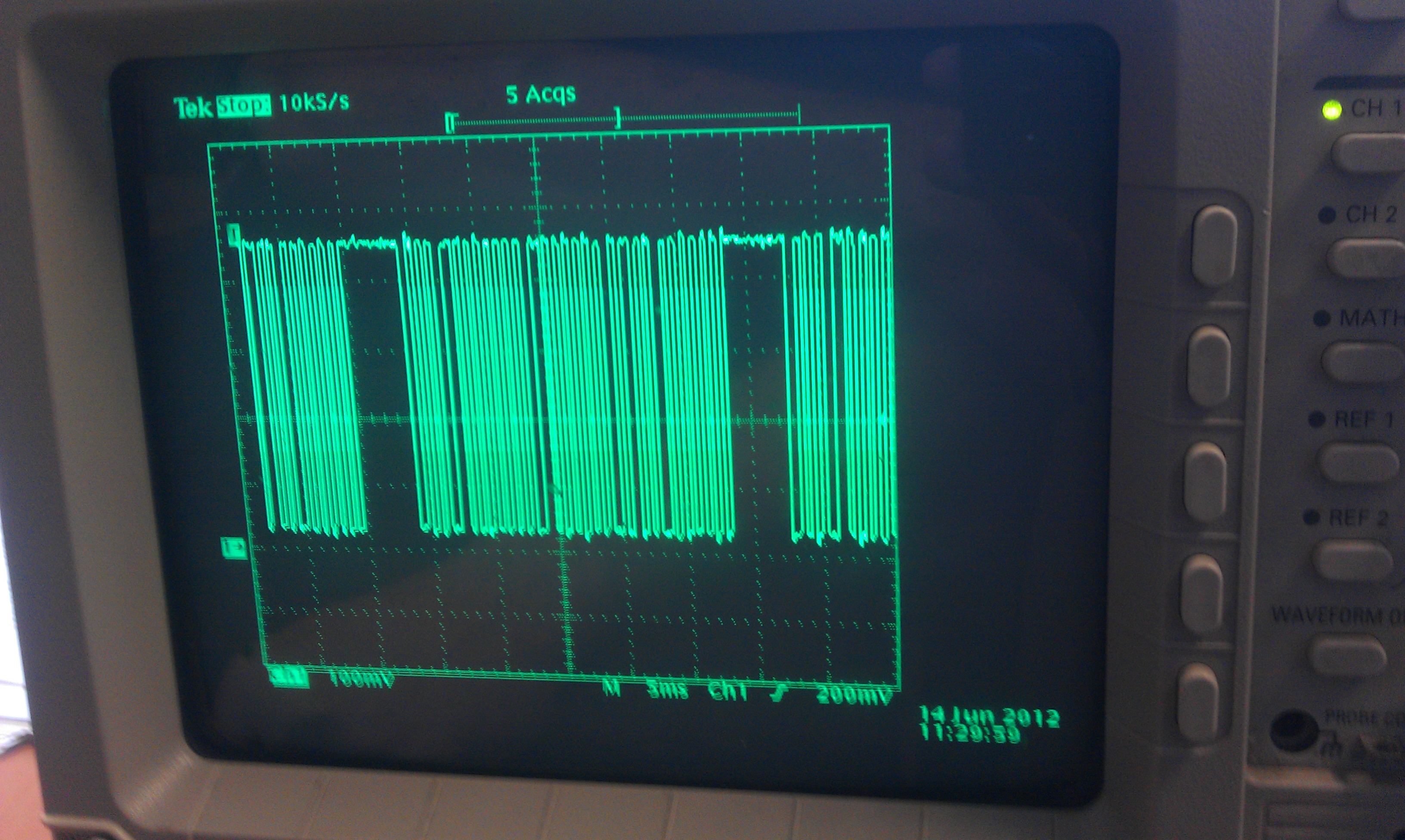
The signal is back the right way up again, and at the right voltage. There’s nothing left to do but put Pi and tank together and see what happens! Find out next time on the Raspberry Tank build diary! :)
Comments
Hi Ian,
I'm attempting to follow your build and just getting started. I'm having trouble finding a 310 ohm resistor. I can get the 390 ohm, no problem - but the 310 ohm doesn't seem to be readily available. Closest I can find at the local Radio Shack is a 330 ohm. Where did you get yours?
Thanks Ian - your raspberry tank build is so cool!
Brad - Salt Lake City, Utah
Thanks!
The resistor values in this circuit don't have to be exactly the same as mine - anything roughly similar will do. The potential divider created by the 310R and 390R resistors ensures that when the transistor is off, the output is roughly 4V, but this 4V is fed into the RX-18 which isn't particularly picky about its input levels. In fact, even with my resistors, the output is rarely exactly 4V as VCC varies between 6 and 8 volts depending on how full the battery is.
So long as you get a resistor close to 310 Ohms -- 330 will be absolutely fine -- you shouldn't run into any problems.
If anyone needs the part numbers for the above boards ( because I didnt have a clue) I posted on the CNC forum I use to help me find them .. hope I dont step on anyone toes Ian only I'm no electronics expert and there may be more like me :) mycnc.co.uk
The 10k is simply to limit the amount of current from the GPIO pin through the transistor. Without a resistor the GPIO pin would see an almost short to gnd, leading to the Pi getting toasted (should have a certain degree of protection I would think) or the transistor gettign cooked (due to the limited amount of current, I;d expect the Pi to die first). Anything in the 1k-10k range should work fine.
The other 2 resistors are being used as a voltage divider to reduce the 7.2V to aprox 4V. One thing to note is the 310R will basically be connected direct to ground when the transistor is switched on, so you want to ensure it's got a high enough power rating.
So current is 7.2V/310R = 23mA, then Power is 7.2V*0.023A=0.16W. An 1/8W resistor is only 0.125W, so you may want a 1/4W resistor for durability, or two 1/8w in series or parallel, if you can't guarantee long periods of being the transistor being switched on.
Just done a quick search, and 1/4W are actually cheaper. I've been doing too much with SMD lately where 1/8W is normal!
10k - RS own brand 1/4W- 707-7745 12p for 10
390R -RS 1/4W - 707-7634 16p for 10
309R (nearest to 310R) - either Vishay 3/5 (0.6)W - 683-3500 -1.25 for 25 OR TE 1/4W - 754-9072 1.07 for 5
The TE have a tighter tolerance (0.1% v 1%)
The correct web address for the cnc forum is www.mycncuk.com, not Mr Beans place :).
.Me
Thanks for going to the trouble of explaining the circuit better -- and for finding the part numbers (I had all the components lying around, so I never had to look them up!)
The Raspberry Pi's GPIO pins have no protection at all, so if you try to draw or push more than 16mA per pin (50mA for the 3v3 power pin) you stand a reasonable chance of toasting your Pi.
Regarding power dissipation in the 310R resistor, since the full voltage is across this resistor when we are trying to send a "low" signal to the RX-18, this is probably the case slightly more than 50% of the time. I used a 1/4W resistor and have had no problems -- I haven't noticed it being particularly warm.
Hi thanks Ian for the reply .. Lee sorry I thought maybe URL links wouldnt work I stand corrected .. hope you are feeling better .. Lee's one of the forum moderators on mycncuk.. so I want to keep him happy lol :)
BTW I didnt find the parts numbers the post is by M_C from the forums ..